Scope: U.S. general-industry manufacturing. Equipment-specific rules and OSHA-approved State Plan requirements may differ.
Machine guarding and hazardous-energy isolation solve different problems
A palletizing robot may be stationary while a photoeye waits for the next carton. The conveyor may also be stopped. Neither condition proves that the system is isolated. A downstream signal, automatic reset sequence, another machine, or a person at a remote control station may cause motion. A gravity-loaded robot arm or tensioned belt can also move after motor power is removed.
The essential questions are:
- During operation, what prevents a person from reaching dangerous motion? That is the machine-guarding and safety-control problem.
- When someone needs to enter, clean, adjust, or repair equipment, what prevents hazardous energy from injuring that person? That may be a lockout/tagout (LOTO) problem.
- When controlled motion is indispensable to a task such as programming, how is that task made safe? The answer calls for a task-specific risk assessment, applicable OSHA rules, and validated engineering controls, not simply a mode switch.
For U.S. general industry, 29 CFR 1910.212 addresses machine guarding. 29 CFR 1910.147 addresses hazardous-energy control during covered servicing and maintenance. OSHA's robotics standards page states that there is no separate federal OSHA standard dedicated specifically to the robotics industry. Applicable electrical, equipment-specific, and state-plan rules also matter.
OSHA regulations are enforceable. The contemporary ANSI, ISO, and ASME standards discussed below provide recognized technical methods but do not automatically become federal regulations simply because they are the newest editions. An expressly incorporated edition, contractual specification, or state law needs to be evaluated separately.
Quick decision guide: During production, prevent access to reachable nip, crush and tool hazards through effective guarding and validated protective functions. Before cleaning, unjamming, adjustment or repair with possible exposure to unexpected energization or stored energy, determine whether 1910.147 applies and use the needed energy-control method; neither an E-stop nor an interlock is physical isolation. Where a task genuinely calls for controlled robot motion, establish an engineered, validated operating arrangement and separately assess any servicing exposure. The task-specific distinctions and narrow exceptions are developed in Sections 6–7.
Use this guide by task: Sections 1–3 explain hazards, risk assessment and safeguards; Sections 4–5 distinguish stops and collaborative applications; Sections 6–7 cover teaching, servicing and the isolation decision; Section 8 contains the 20-point inspection form; Sections 9–10 address training, incident learning and editions. The risk-closure and safety-function test forms are blank working templates, not completed machine certifications.
1. Recognize hazards across the complete robot-and-conveyor cell
Robot motion, tooling, and neighboring equipment
The hazardous space is larger than the path seen during one normal cycle. Assessment needs to account for reachable robot poses, programmed and fault-related movement, the back of the manipulator, end-of-arm tooling, carried products, fixtures, transfer points, and adjacent machinery. Relevant exposures include:
- Crushing and trapping: Between an arm and a column, fixture, fence, pallet, or stationary machine; under an raised axis or load.
- Struck-by hazards: Moving arms, tools, grippers, dropped parts, or loads released by vacuum or clamp failure.
- Cutting, puncture, and thermal exposure: Weld guns, sharp sheet-metal blanks, cutters, hot products, and process equipment.
- Unexpected startup: Automatic cycle restart, restored sensor signals, remote commands, program branches, or sequencing with conveyors and other machines.
- Stored energy: Gravity, counterbalances, compressed air, hydraulics, springs, vacuum, suspended tooling, and residual electrical energy.
OSHA's Industrial Robot Systems Technical Manual specifically addresses hazards created by manipulators, end-effectors, peripheral equipment, programming, and failures in integration. NIOSH's robotics overview likewise identifies the potential for injuries even where automation removes workers from other hazardous tasks.
ISO 14118:2017 provides voluntary machinery-design principles for preventing unexpected start-up from supplied and stored energy, including gravity and compressed springs. Its publisher states that it does not establish a universal performance level or prescribe the specific solution for every machine. Apply any such design guidance alongside, not in place of, OSHA's governing safeguarding and energy-control requirements.
Conveyor in-running nip points
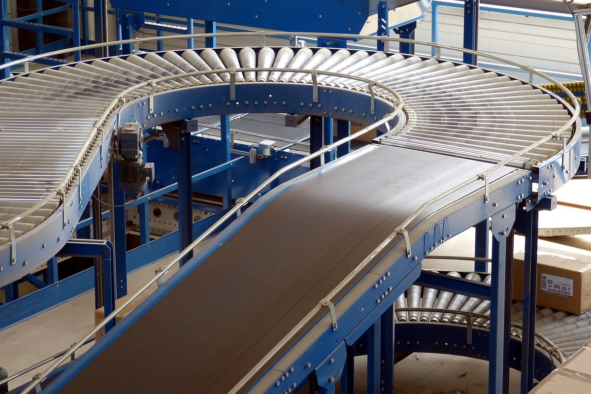
An in-running nip point is a location where moving material or components can draw in a hand, glove, sleeve, hair, tool, or other object. Examples include a moving belt meeting a head or tail pulley; belt-to-roller, chain-to-sprocket, and certain roller-transfer interfaces. Additional hazards include protruding drive parts, falling loads, shear points at transfers, sudden belt movement, and gravity or tension take-ups.
Guard the actual draw-in or reach hazard; a fence that prevents one route to a roller but leaves access from below, behind, above, or from a maintenance platform may be insufficient. Do not assume that a slow conveyor is harmless: the injury mechanism depends on nip geometry, available force, entanglement, and the ability to escape, not speed alone.
OSHA 1910.212(a)(1) expressly identifies ingoing nip points and rotating parts as hazards requiring guarding. 1910.219 may separately apply to particular mechanical power-transmission components. OSHA's amputation-prevention publication illustrates conveyor nip, shear, and entanglement hazards.
2. Assess each task: not just the machine model
An integrator's initial risk assessment is essential evidence, but the employer needs to account for how the installed application is actually used. Two otherwise identical robots can have different risks because their tools, part shapes, neighboring conveyors, approach directions, layouts, and access tasks differ.
A task-based assessment should:
- Define boundaries: Robot, tooling, conveyor sections, upstream/downstream interactions, fences, passages, energy sources, operating modes, and the full set of personnel who could enter.
- List lifecycle tasks: Automatic production, replenishment, quality checks, cleaning, jam clearing, teaching, restart, troubleshooting, repair, modification, and decommissioning.
- Identify foreseeable access and failures: Misfeeds, sensor faults, loss/restoration of power, an open guard, manual override, dropped material, and a second worker entering unseen.
- Estimate risk before controls: Consider injury severity, exposure frequency/duration, and the likelihood or possibility of avoidance. Use a consistent, documented methodology.
- Select risk reduction: First eliminate hazardous configurations where practicable, then use guards, safety functions, engineered isolation and task-specific procedures. Training and PPE are supporting measures, not substitutes for feasible safeguarding.
- Verify and validate: Confirm the installed safeguards and safety-related control functions actually perform as needed, including stopping behavior, access time, reset/restart logic, and relevant failure responses.
- Record residual risk and ownership: Document assumptions, limitations, actions, responsible people, and the conditions that trigger reassessment.
Use ANSI B11.0-2023, ISO 12100:2010, and the 2025 ANSI/A3 industrial robot standards as technical frameworks. OSHA's robotics technical manual also recommends application-specific task-based risk assessments and validation. There is no general statement in 1910.212 that every robot cell needs to maintain a particular named ANSI risk-matrix form.
Task-by-task risk matrix (hypothetical screening, not a certified risk assessment)
The following ordinal method is an illustrative screening aid, not a scoring scheme prescribed by OSHA, ANSI, or ISO. It keeps severity, exposure and avoidance separate so an assessor can identify the assumptions behind each decision:
- Severity (S): S1 = minor/reversible; S2 = serious injury; S3 = permanent disability or death is credible.
- Exposure (E): E1 = unusual/infrequent task; E2 = occasional intervention; E3 = frequent or repeated access.
- Avoidance (A): A1 = a worker may plausibly perceive and avoid the event; A2 = rapid, trapping, or poorly perceptible event makes avoidance difficult. This is a scenario judgment, not proof that the task is safe.
- Disposition: “Priority engineering review” means controls need to be assessed and validated before work proceeds where injury exposure is present. “Verify boundaries” means first establish whether the worker can actually reach the hazard. There is no mathematical conversion from S/E/A to an ANSI performance level or acceptable residual risk.
| Task and assumed access | Credible initiating event and consequence | Screening S/E/A* | Initial disposition | Safeguard or energy-control decision | Needed evidence before residual-risk acceptance |
|---|---|---|---|---|---|
| Automatic palletizing; operator outside perimeter | Arm or carried pallet load reaches an accessible opening; crush injury | S3 / E1 / A2 | Verify boundaries | Fixed perimeter guarding, protected transfers, suitable safety functions | Reach survey from all approaches; protected opening and stop-function validation |
| Frequent manual carton feed | Hand enters robot or conveyor hazard before stop; crush or draw-in | S3 / E3 / A2 | Priority engineering review | Eliminate reachable nip; engineered presence sensing/interlock; guarded transfer | Recorded stopping performance, approach assessment, reset/restart tests |
| Observe equipment through an intact external window | Projected part escapes cell; impact injury | S2–S3 / E3 / A1–A2 | Verify boundaries | Containment and safe viewing location; no entry | Window/containment suitability for actual process; condition inspections |
| Teach inside robot cell | Unintended robot/peripheral movement traps programmer | S3 / E2 / A2 | Priority engineering review | Controlled manual mode, enabling device, safe motion and clearance; evaluate LOTO for concurrent servicing | Mode, authority and enabling tests; peripheral isolation/control review |
| Wipe accessible photoeye near powered roller | Restored photoeye signal starts conveyor during reach-in | S3 / E2 / A2 | Priority engineering review | Move service point outside danger; otherwise evaluate 1910.147 and proven exception criteria | Task-specific reach assessment, isolation or documented effective alternatives |
| Clear transfer jam | Carton releases and adjacent drive unexpectedly moves; hand drawn into nip | S3 / E2 / A2 | Priority engineering review | Engineered external clearing or covered LOTO; exception only when established | Energy-source list, task analysis, proof of controls and isolation verification |
| Replace roller during planned shutdown | Tension take-up moves or connected drive energizes; crushing | S3 / E1 / A2 | Priority engineering review | Group/section isolation and restraint of stored mechanical energy | Equipment-specific LOTO and verified load/tension support |
| Change pneumatic gripper | Trapped pressure actuates clamp or suspended tool falls | S3 / E1 / A2 | Priority engineering review | Lockout where applicable; discharge air; block/support loads | Verified depressurization and positive mechanical restraint |
| Diagnose potentially exposed live electrical parts | Electric shock/arc incident or unintended actuation | S3 / E1 / A2 | Priority engineering review | Analyze 1910.333 and mechanical energy control separately | Qualified electrical assessment and documented safe-work conditions |
| Collaborative robot carrying sharp steel blank | Tool/workpiece strikes or traps a worker; cut or crush | S3 / E3 / A2 | Priority engineering review | Redesign tool and fixture; validated collaborative safety functions and other safeguards | Contact/entrapment assessment, applicable validation tests, acceptance record |
*The values depend entirely on the stated hypothetical assumptions; real facility conditions can change every entry. A responsible team needs to document its chosen method, input evidence, protective measures, residual-risk assessment and approval. No row above is declared acceptably safe. These examples illustrate the task-based approach discussed in OSHA's robotics technical manual, ANSI B11.0-2023 and ISO 12100:2010, without implying those standards use this exact screening shorthand.
Task risk-control closure and residual-risk decision record
Complete a separate record for each actual task and machine configuration. The initial S/E/A screening is a prompt for analysis, not an automatic acceptance threshold. A residual rating needs to be reassessed after controls are implemented and verified; it needs to never be copied from the example matrix or inferred merely because a guard is installed.
| Task / configuration / revision | Initial hazard and S/E/A, with evidence | Implemented safeguard or isolation | Validation evidence and unresolved limitations | Reassessed residual S/E/A and basis | Disposition and restrictions | Assessor / approving authority / date / review trigger |
|---|---|---|---|---|---|---|
| ______ | ______ | ______ | ______ | ______ | [ ] Pending · [ ] Not accepted · [ ] Accepted for defined scope | ______ |
| ______ | ______ | ______ | ______ | ______ | [ ] Pending · [ ] Not accepted · [ ] Accepted for defined scope | ______ |
Decision rule for this working template: Select Pending until the relevant engineering and task checks are complete; select Not accepted when controls are inadequate or their effectiveness is unproven. Acceptance needs to be explicitly justified against the employer's documented risk criteria, applicable requirements and actual validation evidence by an authorized person. Record restrictions, affected workers, actions still open and triggers such as a new tool, program, workpiece, speed, guard or conveyor connection. An unsigned or incomplete row is not an authorization to expose workers to the hazard. Neither OSHA nor this example establishes a universal numeric acceptable-risk score.
Worked risk-assessment record: a conveyor transfer jam
Hypothetical assumptions: A motorized upstream belt feeds cartons onto driven rollers, followed by a palletizing robot. Clearing calls for removal of a fixed guard and a hand near an in-running nip. The upstream drive can respond to a remote automatic command, and a take-up retains belt tension.
- Task boundary: Access to the guarded transfer, not normal monitoring from outside. Include the robot, both conveyor drives and any stored tension or suspended load that can affect the work.
- Pre-control exposure: Entanglement/crushing is credible; S3/E2/A2 in the illustrative scale above. An E-stop or stopped display is not energy isolation.
- Preferred redesign: Explore a removable product-access tray or jam-clearing point that permits work outside all hazardous movement; validate that no new reach-through exists.
- If entry remains necessary: Evaluate the task under 1910.147. If the minor-servicing exception is not fully established with effective alternative measures, use an equipment-specific energy-control procedure covering connected sources, stored tension and verification.
- Verification before release: Confirm the actual isolation boundaries, blocking/restraint, employee control of devices, and effectiveness of the chosen method. Record who validated the safeguards; do not mark residual risk “low” by assumption.
3. Design machine guards and access points for the real task
Fixed guards
Fixed fencing, covers, and nip-point barriers are appropriate where routine access is unnecessary. They should be secured, strong, and designed so personnel cannot reach over, under, through, or around them into the hazard. A guard may not introduce a new cutting, snagging, or trapping hazard. Protect all relevant approach directions, including raised platforms and conveyor return runs.
OSHA 1910.212(a)(2) addresses guard attachment and the requirement that guards not present a hazard themselves. ISO 14120:2015 provides technical guard-design guidance; it is not a substitute for examining actual reach and hazard geometry.
For reach-through and reach-around decisions, ISO 13857:2019 addresses distances between protective structures and hazardous zones for upper and lower limbs. Its published scope has limits: it does not by itself address climbing over a guard, and its tabulated distances are not a universal answer for every hazard, worker or access task. Determine the applicable geometry using the full current technical standard and the site risk assessment; no distance is assumed in this guide.
Movable guards and safety-rated interlocks
An interlocked gate can request a protective stop when opened. Whether it also needs guard locking, monitored standstill, prevention of unexpected restart, trapped-person prevention, or additional presence detection depends on the risk assessment. A basic position switch connected only to an ordinary programmable controller does not, by that fact, establish a safety-rated function.
An engineer should specify and validate the entire safety function: sensor/interlock, wiring and logic, output elements, actuator stopping, diagnostic behavior, fault response, and restart conditions. Needed reliability or performance is derived from risk assessment and the applicable design standard; there is no universal OSHA-mandated performance level for every robot-cell gate.
For a guard that a worker can open and reach through, evaluate whether the machine stops before a person can reach the hazard. If hazardous motion continues longer than access takes, a properly engineered guard-locking or other protective arrangement may be necessary. A gate switch does not by itself prove that all connected equipment is stationary or that trapped energy is controlled. The type and reliability of the chosen interlock, foreseeable defeat, and any safety-related bypass or controlled maintenance mode call for design review.
Distinguish the functions commonly described in a robot safety file:
| Function | What it is intended to do | Critical limitation |
|---|---|---|
| Protective stop from an interlock or presence sensor | Bring relevant hazardous motions to a defined protected condition | Other axes, conveyors, suspended loads or energy sources may remain hazardous |
| Safety-related monitored speed / motion limit | Detect or constrain a specified motion condition as part of a validated safety function | Ordinary program speed settings are not evidence of safety-rated speed limitation |
| Safe torque off (STO), when provided and properly integrated | Prevent generation of motor torque through a defined drive safety function | Not a physical electrical disconnect or comprehensive stored-energy control; gravity and other sources can remain |
| Monitored standstill (term used in revised 2025 robot guidance) | Maintain and monitor an intended stopped condition, potentially with power present | Not inherently an OSHA 1910.147 energy-isolating device |
| Emergency stop | Initiate an emergency stopping response | Does not replace prevention of access or hazardous-energy isolation |
| Lockable energy-isolating device used under LOTO | Physically prevent transmission/release of the isolated source of energy in accordance with the procedure | Needs to cover all relevant hazardous sources and residual energy, not merely one electrical motor |
The distinctions follow OSHA's energy-isolating-device definition, its robotics technical manual, and the current A3 R15.06 publisher description. They are functional descriptions, not a substitute for consulting a particular drive's certified safety manual.
Applicable technical references include ANSI B11.19-2019 (R2024), ANSI B11.26-2024, ISO 14119:2024, ISO 13849-1:2023, and ISO 13849-2:2012 for validation. The appropriate edition and contractual design basis should be documented.
Light curtains, scanners, and stopping distance
Presence-sensing devices may guard access points where materials or workers need to pass. They need to be chosen for the foreseeable approach, detection capability, environmental conditions, stopping time, and possibility of bypass. A device installed too close to hazardous motion may detect a person but fail to stop the hazard before the person reaches it.
Spacing, response time, muting, blanking, and reset logic call for engineered calculation and validation. Do not copy an arbitrary distance, sensor field, or stopping time from another plant. ISO 13855:2024 covers safeguard positioning principles. Account for conveyors and tooling that can continue moving after the robot stops.
Muting and blanking are not general permissions to defeat a sensor. They call for application-specific design, detection of intended material passage, an assessment of human access during the allowed state, and validation of faults and restoration. A product passing through an opening is different from a worker following it into the same opening. A protective device that is frequently blocked or misaligned should prompt review of the machine layout rather than routine bypass.
Restart and escape from inside the cell
Design for the possibility that someone remains behind a closed gate, outside the detection field, or hidden behind pallets. If warranted, use measures such as whole-area presence detection, controlled manual reset with a clear view, trapped-key systems, and means of escape. The responsible engineer needs to verify that resetting a device cannot itself cause an unsafe restart. Do not assume that the door interlock alone detects an occupant already inside.
Commissioning and change-control validation: what needs to be demonstrated
Validation means more than confirming that a light on a safety controller changes state. An authorized, qualified team should document the intended safety functions, the design basis, performance requirements derived from the risk assessment, test methods and results. Tests that could create exposure needs to be performed under a controlled commissioning plan with appropriate safeguards; this table is not an instruction to deliberately create dangerous failures during production.
| Function or challenge | Evidence to obtain | Acceptance decision (site-specific, not a universal number) |
|---|---|---|
| Gate opened during protected automatic operation | Actual response of robot, gripper, conveyor and other integrated components | Relevant hazards reach their validated safe condition before access; no omitted connected movement |
| Gate closed / interlock reset | Recorded restart logic and possibility of personnel remaining inside | Mere reset or loss/restoration of a signal does not create hazardous, uncommanded restart |
| Light curtain or scanner detects approach | Documented detection coverage, sensor response, machine stopping performance, position and foreseeable approach | Separation/coverage are adequate for the actual approach geometry and measured system behavior |
| Material passage through muting or blanking zone | Authorized sequence, zone state, failure responses and human-access analysis | No foreseeable human bypass or hazardous unprotected reach introduced by the material logic |
| Power loss and restoration | Specified and observed safe state, retained-load behavior, controller/drive restart response | Machine remains safe during transitions and does not restart hazardously without the needed action |
| Failure of monitored safety component | Review of specified fault detection, diagnostics and response using a controlled validation method | Fault response matches the needed safety function and design assumptions |
| Teach/manual selection and enabling device | Demonstration of mode authority, enabling behavior, permitted motion and peripheral controls | The validated manual operation cannot silently restore unexpected automatic motion |
| Emergency-stop activation and reset | Responses of every relevant drive and conveyor, accessibility, reset logic | Intended stopping response and manual reset function correctly; emergency stop is not treated as isolation |
| Change to end-effector, workpiece or program | Change record, affected tasks and retesting of safety functions | Previous risk assumptions and protective measures remain valid, or a new assessment and validation are completed |
For each test, keep a record of the function ID, equipment/cell ID, revision, test condition, expected result, observed result, discrepancies, evaluator, date and disposition. Where a result fails the approved criterion, do not authorize the affected hazardous operation until suitable interim risk controls and corrective validation are established. Determine when an additional independent design review is appropriate. OSHA's robotics technical manual specifically discusses validation of safety-related control parts, sensor operation and contact-event assessments; ISO 13849-2:2012 addresses validation of safety-related control systems.
Safety-function verification and validation record: blank site form
Use one form per defined safety function and validation condition. It is an evidence-capture template, not a commissioning protocol, an instruction to induce unsafe faults, or a substitute for the applicable design standard.
| Record field | Site entry |
|---|---|
| Facility / cell / machine identification | ______ |
| Safety-function ID and description | ______ |
| Equipment, logic, firmware and documentation revision | ______ |
| Related task assessment and hazard ID | ______ |
| Needed safe state and affected connected equipment | ______ |
| Design basis: applicable standard/edition, manufacturer guidance, approved specifications | ______ |
| Needed performance/acceptance criteria, with source | ______ |
| Qualified test team, roles and independent review if needed | ______ |
| Controlled test conditions and protections against exposure | ______ |
| Test or challenge condition, with approved procedure reference | ______ |
| Expected response, including fault, reset and restart behavior | ______ |
| Actual observed response; measured values, units, instrument ID/calibration reference if relevant | ______ |
| Difference from expected response, deviation/action ID | ______ |
| Test disposition | [ ] Pass · [ ] Fail · [ ] Not tested, reason: ______ |
| Correction and retest evidence/date | ______ |
| Affected operation disposition | [ ] Release for identified scope after acceptance · [ ] Withhold release |
| Validator name / role / signature / date | ______ |
| Release authority name / role / signature / date | ______ |
| Limitations and next verification/reassessment trigger | ______ |
Release gate: A “Pass” calls for supporting observations against documented, site-specific criteria; a skipped test is not a pass. A failed, incomplete or unsubstantiated safety function cannot be treated as validated. Any provisional operating restriction calls for a separately supported risk decision that protects workers, not an unchecked assumption that reduced-speed or manual mode is safe. Maintain traceability from the original hazard to the function, evidence, corrective action and final authorization.
4. Emergency stops are supplementary protective measures
An accessible emergency-stop button or conveyor pull cord is intended to initiate an emergency stopping response. It does not physically exclude personnel from moving machinery. It does not necessarily remove electrical or other stored energy. It does not replace a needed fixed guard, interlock, or OSHA energy-isolation procedure.
OSHA's materials-handling guidance discusses conveyor stop buttons, pull cords, and safe restart, and ISO 13850:2015 concerns emergency-stop function design. Determine the applicable requirements for each conveyor: some OSHA rules are specific. For example, 29 CFR 1910.261(c)(15)(iv) imposes a particular emergency-stop provision in pulpwood-handling operations. That provision is not a universal rule for every manufacturing conveyor.
Inspection should verify that emergency stops and pull cords are reachable, function as designed, remain latched/reset as intended, and integrate correctly with downstream and upstream machines. An emergency-stop test cannot replace interlock validation or an isolation verification.
5. Traditional industrial robots and collaborative applications
Traditional robot applications ordinarily control exposure by separating people from automatic motion with fencing, gates, and presence sensing. A collaborative application intentionally permits a defined degree of human-robot interaction under assessed conditions; it is not simply a product labeled “cobot.”
Examples of collaborative safety techniques include speed-and-separation monitoring, power-and-force limiting, hand guiding, and monitored standstill. The engineering decision concerns the whole application, including end-effectors, workpieces, fixtures, conveyors, and foreseeable contacts. A low-force arm carrying a pointed tool, sharp metal blank, or hot part can still present a severe hazard. Likewise, a person could be trapped against a rigid fixture at a low operating speed.
Consider hypothetical example A: A collaborative robot places thin steel blanks into a fixture. The manufacturer's arm may have force-limiting functions, but the sharp blank and fixture create cutting and trapping hazards. A valid assessment considers part edges, contacts at every relevant reach, workpiece release, and possible additional guarding, not merely the arm's nominal payload or collaborative designation.
The current ANSI/A3 R15.06-2025 Parts 1 and 2 adopt ISO 10218-1:2025 and ISO 10218-2:2025. ANSI/A3 R15.06-3-2025 addresses users of industrial robot cells. ISO/TS 15066:2016 remains a published collaborative robotics technical specification. The revised 2025 ANSI/A3 standard incorporates collaborative-operation material; do not assume that older technical terminology or tables have been carried over unchanged. Use the complete applicable editions to establish and validate any contact limits for the actual application.
6. Teach mode, troubleshooting, and maintenance
Teaching calls for controlled motion, not unrestricted automatic operation
Some programming tasks call for a trained person to be inside a protected cell while the robot moves. A designed teaching arrangement may use a selected manual operating mode, reduced and safety-monitored motion, a three-position enabling device, hold-to-run behavior, controlled authority, and adequate clearance. Peripheral conveyors, grippers, clamps, and fixtures need to be included in the risk assessment.
With a properly designed three-position enabling device, its intermediate held position enables specified controlled motion; releasing or fully squeezing it initiates the specified protective response. The programmer needs to understand the robot's active coordinate system, expected travel, tool and workpiece sweep, possible back-side motion, and the behavior of all linked equipment. Avoid positioning a person between the robot's possible motion and a fixed obstruction. Access permission, mode authority and pendant possession should be clear, particularly when more than one technician is present.
OSHA's robotics technical manual describes a reduced teaching speed of about 250 mm/s (10 in/s) as a guidance reference in the manual's earlier standards context. That figure is not presented here as a universally enforceable OSHA 1910.212 speed limit, a guarantee against crushing, or proof of conformity to ANSI/A3 R15.06-2025. The specific speed, safety monitoring, clearance, associated process hazards and other protective measures need to be evaluated for the installed task and current applicable design basis. Even slowly moving equipment can trap a worker against a fixture.
Distinguish manual teaching, attended program verification, ordinary troubleshooting, and mechanical/electrical servicing in the task list. Each changes the foreseeable exposure. A manual-mode selector, enabling device or monitored standstill is not automatically an OSHA-recognized energy-isolating device.
Teaching and maintenance are different tasks. If the person begins replacing a motor, disconnecting a gripper, reaching into a jam, or performing other covered servicing, reassess the task under 1910.147 before continuing. A task cannot be exempted from energy isolation merely by renaming it “teaching” or “troubleshooting.”
Troubleshooting that genuinely calls for energy
First determine whether the fault can be diagnosed from outside the hazard zone or with the system deenergized. If inspection or repair requires entry into a danger zone, apply the appropriate energy-control requirements. When testing or positioning covered equipment truly requires temporary energization, follow the explicit sequence in 1910.147(f)(1): clear tools/materials, remove employees, remove isolation devices under the standard's rules, perform the test, and deenergize and reapply controls before more servicing.
Work exposing employees to live electrical parts calls for a separate analysis under 29 CFR 1910.333. The OSHA 1910.147 framework expressly excludes certain electrical-shock exposures governed by Subpart S; mechanical and pneumatic hazards may still coexist. Do not treat an energized electrical diagnosis as permission to expose workers to moving machinery.
Where employees work on or near exposed live parts, 1910.333 generally calls for deenergization unless its conditions for work without deenergization are met; the work practices, qualification, and verification provisions need to be evaluated on their own terms. A drive display showing “off,” a released E-stop, and a motor that is not moving do not prove that live conductors are safe to touch. Conversely, an electrical safe-work plan alone may leave a mechanically raised axis or pressurized gripper uncontrolled.
7. Clearing conveyor and robot-cell jams
Consider hypothetical example B: A case sealer discharges onto a motorized roller conveyor feeding a palletizing robot. A carton wedges at the transfer. A worker stops the conveyor and opens a gate to pull the carton free. The robot is stationary, but the upstream drive, downstream drive, robotic cycle, and an raised gripper may still hold or restore hazardous energy.
The correct sequence begins with task definition: Can the obstruction be removed from a designed, guarded external access point without entering or reaching into danger? If not, evaluate the job as servicing/unjamming. Under 1910.147(a)(2)(ii), covered servicing during production includes situations involving bypass of guarding or entry into danger zones. A narrow minor-servicing exception may apply only when the work is routine, repetitive, integral to production, and performed using alternative measures that provide effective protection. Those conditions must actually be established; “quick jam” is not an exemption category. OSHA's minor-servicing guidance and enforcement directive discuss this analysis.
If the exception is not substantiated, use the equipment-specific energy-control procedure. Include all connected sources able to affect the task; relieve, restrain, or otherwise render safe tension, gravity loads, pneumatic pressure, spring force, and similar energy. Verify isolation before reaching in. Do not rely on an operator's promise not to restart or on a software alarm screen.
Three contrasting task determinations:
| Scenario | Preliminary regulatory assessment | What still needs to be established |
|---|---|---|
| Worker wipes a sensor from a designed external position, without any body part exposed to a point of operation or associated danger zone and without hazardous unexpected energy exposure | General guarding and safe operation still apply; the described task may not trigger 1910.147 | Confirm access geometry, possible automatic motion and absence of hazardous energy exposure; do not treat “outside the fence” as conclusive by itself |
| Worker makes a minor, routine and repetitive in-cycle adjustment that is integral to production | The minor-servicing exception might apply | Employer needs to establish every relevant exception condition and effective alternative protection, including foreseeable restart and reach hazards; mere routine frequency is insufficient |
| Worker removes a conveyor guard and exchanges a powered roller near a tension take-up | Covered servicing with a foreseeable startup/stored-energy hazard; apply 1910.147 unless a legally applicable exclusion is demonstrated | Identify and isolate connected drives, secure tension/weight, apply personal/group devices and verify before work |
This distinction follows 1910.147(a)(2)(ii) and OSHA's minor-servicing interpretation. It is task-specific, not a blanket rule by equipment brand, production shift, or duration. Note separately that the eight-condition exception to documenting an energy-control procedure in 1910.147(c)(4)(i) is a different provision; it does not eliminate the underlying requirement to lock out when applicable, and it rarely maps neatly to a complex multi-energy robot/conveyor cell.
Practical energy-isolation decision flow
Follow each decision in order. Record the task-specific basis for each decision.
- Define the task and sources. Identify all equipment that can affect the worker, including connected conveyors, robot axes, tooling and stored energy.
- Is there exposure to electrical conductors or equipment governed by Subpart S? If yes, establish the applicable 1910.333 work practices with a qualified electrical assessment. In either case, continue to Step 3 for mechanical and other hazardous energy; electrical controls alone do not settle those hazards.
- Could unexpected start-up, motion, or energy release injure someone during this task? If no, verify that conclusion and maintain the applicable machine guards and other rules. If yes, go to Step 4.
- Is this servicing or maintenance covered by 1910.147, including work during production involving guard bypass or entry into a danger zone? If no, apply applicable safeguarding and task-specific requirements. If yes, go to Step 5.
- Is every condition of the narrow normal-production minor-servicing exception actually met, with effective alternative protection? If yes, document and verify those task-specific safeguards before proceeding. If no, physically isolate all applicable sources, apply compliant lockout/tagout, render stored energy safe and verify the isolation before covered servicing.
- After lockout/tagout, is temporary energization genuinely needed for testing or positioning? If yes, use the limited sequence in 1910.147(f)(1), protect people during testing, then deenergize and reapply the controls before further servicing. If no, keep energy isolation effective throughout the work. Release equipment only under the applicable return-to-service procedure.
Interpretation: Electrical-shock controls under Subpart S and physical hazardous-energy controls for mechanical/process hazards may both apply to one job. A “no” on unexpected energy does not override equipment-specific or other OSHA requirements. The minor-servicing exception calls for alternative measures that provide effective protection during the specific task. Assess the relevant access paths, restart mechanisms and stored-energy hazards; an interlock's presence alone does not establish the exception. If applicability remains uncertain, withhold the affected work and obtain a task-specific determination. Adapt this decision aid to the equipment's actual isolation and safeguarding procedures.
Machine-specific LOTO sequence for an integrated cell
- Prepare: Authorized employee identifies the task, energy sources, affected workers, connected machines, and stored energy, including upstream and downstream conveyors and robot tooling.
- Notify and shut down: Use the established orderly shutdown; avoid creating a new hazard such as an unsupported falling load.
- Isolate: Locate and operate the applicable physical energy-isolating devices for each source. A push button, selector switch, interlock, or routine control command is not an energy-isolating device under 1910.147(b).
- Apply personal or group lockout/tagout: Use devices and responsibilities compliant with 1910.147(c) and (d). If tagout is used, the standard's separate conditions apply; a tag alone is not equivalent to a physical lock by assertion.
- Render stored energy safe: Discharge, restrain, block, support, or otherwise make hazardous residual energy safe. Consider reaccumulation and the need for continued verification.
- Verify isolation: Before servicing, the authorized employee verifies that isolation and deenergization have been accomplished. Use an appropriate method for each energy source; do not assume a touchscreen status is proof.
- Complete work and restore safely: Check integrity and tool removal, account for people, remove devices under the rules, notify affected employees, and restore through the designed restart procedure.
These are the elements of 1910.147(d) and (e), simplified for planning, not a ready-to-use isolation map. Group work, shift changes, and contractor coordination invoke additional requirements in 1910.147(f)(2)–(4). Electrical exposures require applicable Subpart S procedures as well.
Group work, personnel changes and controlled testing
For a cell with separate mechanical, electrical and pneumatic trades, a single central lock or sign-in sheet does not automatically provide every worker the protection required by 1910.147(f)(3). The group procedure must provide protection equivalent to a personal device, identify primary responsibility, coordinate the work and provide for individual employee participation as the paragraph specifies. Under 1910.147(f)(4), shift or personnel changes require specific continuity arrangements so protection is not lost when one crew leaves and another takes over. Outside contractors and the host employer must exchange relevant procedures under (f)(2).
When temporary energization is necessary for testing or positioning during covered servicing, 1910.147(f)(1) provides a specific sequence; it is not a general “run it with the guard open” exception. Clear tools and workers as required, remove lockout/tagout devices according to the standard, test, then deenergize and reapply energy controls before further servicing. Plan the boundary, communications and responsibility for each transition. Do not have a worker remove another worker's personal lock outside the narrow employer-directed removal procedure in 1910.147(e)(3).
OSHA's October 21, 2024 interpretation is decisive when power is said to be indispensable. OSHA explains that 1910.147(f)(1) permits only the limited reenergization needed to test or position equipment, with the required transition sequence and protection against hazardous exposure. It expressly rejects treating the general alternative methods definition in ANSI machinery-energy standards as an automatic substitute for OSHA isolation obligations outside applicable regulatory exceptions. The current voluntary ANSI/ASSP Z244.1-2024 is relevant engineering guidance, but compliance with its alternative-method provisions alone does not establish compliance with 1910.147. See the October 21, 2024 OSHA letter, questions 1–2 and the controlling 1910.147 text. This interpretation does not create a new blanket exception or a new legal duty separate from the regulation.
8. Operational machinery-safety inspection checklist
Identification: Facility: ______ · Cell/equipment ID: ______ · Location: ______ · Guard/safety-function revision: ______ · Date: ______ · Inspector and role: ______ · Operations/maintenance contact: ______
Use: Walk each installation with operations, maintenance, and a competent engineering representative. Mark exactly one result for each line: P = Pass (verified on the installed equipment); D = Deficiency; NA = Not applicable (state why); NV = Not verified. Give the evidence, test record or action ID and assign deficiencies to the corrective-action register. NV is not a pass; an unverified critical safety function may not be treated as effective. This checklist does not establish a universal OSHA inspection interval.
| Inspection item | Select one: P / D / NA / NV | Evidence, test record, NA rationale or action ID |
|---|---|---|
| A current layout identifies the robot's accessible envelope and all connected machinery. | [ ] P · [ ] D · [ ] NA · [ ] NV | |
| Task assessments cover production, setup, teaching, clearing jams, cleaning, repair, and foreseeable failures. | [ ] P · [ ] D · [ ] NA · [ ] NV | |
| In-running conveyor nips, power-transmission parts, transfer shear points, and return runs are guarded where exposure exists. | [ ] P · [ ] D · [ ] NA · [ ] NV | |
| Guards are secured, intact, and free of new reach-through or snag hazards. | [ ] P · [ ] D · [ ] NA · [ ] NV | |
| Access cannot be gained over, below, behind, or through a guard before hazardous motion is controlled. | [ ] P · [ ] D · [ ] NA · [ ] NV | |
| Interlocked gates and any guard locking work as designed, including foreseeable faults and restart behavior. | [ ] P · [ ] D · [ ] NA · [ ] NV | |
| Light curtains/scanners are positioned and validated using actual detection and stopping performance. | [ ] P · [ ] D · [ ] NA · [ ] NV | |
| Means for detection/escape/reset address workers who could remain inside the cell. | [ ] P · [ ] D · [ ] NA · [ ] NV | |
| Safety-related controls are documented, validated, and protected against unauthorized bypass or modification. | [ ] P · [ ] D · [ ] NA · [ ] NV | |
| Robot, conveyor, tooling, gripper, and fixtures respond correctly to protective-stop demands. | [ ] P · [ ] D · [ ] NA · [ ] NV | |
| Emergency-stop devices and pull cords are accessible and operate as designed; reset does not create hazardous restart. | [ ] P · [ ] D · [ ] NA · [ ] NV | |
| Teach/manual mode, enabling devices, motion limits, and authority controls are verified. | [ ] P · [ ] D · [ ] NA · [ ] NV | |
| Collaborative applications assess tool, workpiece, fixture, and possible body contact, not arm label alone. | [ ] P · [ ] D · [ ] NA · [ ] NV | |
| All hazardous energy sources and cross-machine dependencies appear in equipment-specific LOTO procedures. | [ ] P · [ ] D · [ ] NA · [ ] NV | |
| Isolation points are identified, accessible, and capable of needed lockout/tagout controls. | [ ] P · [ ] D · [ ] NA · [ ] NV | |
| Gravity, belt tension, pneumatic/hydraulic pressure, vacuum, and other stored energy can be controlled and verified. | [ ] P · [ ] D · [ ] NA · [ ] NV | |
| Authorized personnel can demonstrate isolation verification and any testing/positioning process. | [ ] P · [ ] D · [ ] NA · [ ] NV | |
| Authorized, affected, and nearby workers receive training appropriate to their LOTO responsibilities. | [ ] P · [ ] D · [ ] NA · [ ] NV | |
| Needed periodic LOTO procedure inspections are completed and certified no less than once a year. | [ ] P · [ ] D · [ ] NA · [ ] NV | |
| Changes, bypasses, faults, near misses, and protective-stop events trigger appropriate review. | [ ] P · [ ] D · [ ] NA · [ ] NV |
Inspection frequency: OSHA 1910.147(c)(6) explicitly requires an inspection of each energy-control procedure at least annually, with the specified inspector/review and certification provisions. That frequency is not an OSHA rule that has every robot interlock or every conveyor guard physically tested once a year. Those verification intervals should reflect applicable equipment-specific standards, manufacturer instructions, use, changes, and assessed risk.
Defect response and corrective-action register
An observed missing guard, failed interlock, unexpected restart, loss of a needed safety function or uncontrolled stored-energy exposure is not simply a paperwork deficiency. Prevent exposure to the affected hazard, apply necessary isolation and escalate for competent engineering/safety evaluation. The actual restriction, such as keeping the affected machine out of service until corrected, needs to follow the identified hazard, applicable employer procedures and verified protective options. Do not continue hazardous operation merely because a repair ticket has been opened.
| Action ID / equipment | Defect and exposure | Immediate protective disposition | Assigned owner / due date | Repair and retest evidence | Authorized closure / date |
|---|---|---|---|---|---|
| ______ | ______ | ______ | ______ | ______ | ______ |
| ______ | ______ | ______ | ______ | ______ | ______ |
Release questions: Have all critical functions affected by the repair or program change been revalidated? Does the current task risk assessment match the configuration? Have isolation devices been removed and employees notified in accordance with applicable procedures? Who has authority to release the equipment? Document a hold/release decision and the rationale, not just a checked box. Retain the signed record according to company policy and applicable obligations; no universal federal retention period for this form is asserted.
9. Training, validation records, and incident investigation
Role-based training
- Operators and material handlers: Guard boundaries, normal operating sequence, stop/restart controls, prohibited reach-in, jam-reporting and escalation, and what to do if a guard is damaged or defeated.
- Robot programmers and integrators: Task-based assessment, operating-mode authority, enabling functions, safe motion, validated safety settings, peripheral equipment, and revalidation after program/tooling changes.
- Maintenance and authorized LOTO workers: Recognition of energy sources and magnitudes, machine-specific isolation, stored energy, group/contractor coordination, verification, and controlled return to service.
- Affected and other employees: Their roles and prohibited interference with locked-out or tagged-out equipment as specified by 1910.147(c)(7).
There is no universal federal OSHA “robot operator certification card” or robot-training expiration date in 1910.212 or 1910.147. Applicable training requirements depend on the work and standard. Retaining documented competence demonstrations and training following changes is a prudent way to establish understanding. See 1910.147(c)(7).
Engineering and inspection record set
Keep the baseline risk assessment and revision history; safety-function descriptions; electrical/mechanical drawings; protective-stop and stopping-time validation; guard and interlock checks; program and safety-parameter change records; energy-control procedures; employee LOTO training certifications; periodic procedure inspection certifications; and maintenance findings. Only characterize a record as OSHA-needed when the applicable regulation expressly calls for it. Other records may be necessary to maintain a defensible engineered system or meet a consensus standard or contract.
Investigate the failed barrier, not just the worker's action
After an injury or serious near miss, protect the scene and preserve information without exposing anyone to additional hazards. Determine the actual task, pre-event equipment state, intended and actual safety functions, interlock/guard condition, sensor logic, accessible approach, program and restart commands, energy sources, relevant change history, and whether needed isolation was used. Interview operators, technicians, and contractors. Examine whether production pressure or inconvenient guard design encouraged bypass. Assign engineering corrective actions, validate their effectiveness, update the assessment, and communicate changes before restart. OSHA's robotics technical manual offers examples of how integration and maintenance failures can create hazardous situations.
10. The legal and technical boundaries of consensus standards
Federal OSHA rules most directly relevant: 1910.212 (guarding); 1910.147 (covered general-industry servicing); 1910.219 (applicable power transmission); and 1910.333 (applicable electrical work). Additional process-specific rules or OSHA-approved state plans may govern a particular installation.
Consensus references and editions:
| Technical subject | Technical reference | What the reference helps evaluate |
|---|---|---|
| Industrial robot design | ISO 10218-1:2025 | Robot design/manufacture |
| Robot integration/cells | ISO 10218-2:2025 | Integration, commissioning, operation, maintenance |
| U.S. robot requirements | ANSI/A3 R15.06-2025 Parts 1–2, R15.06-3-2025 Part 3 | U.S. national adoption and robot-cell user guidance |
| Collaborative applications | ISO/TS 15066:2016 | Supplemental collaborative-system guidance; read alongside the 2025 robot standards |
| Conveyor equipment | ASME B20.1-2024 (ANSI standards catalog) | Conveyor design, installation, operation, maintenance |
| Machinery risk assessment | ANSI B11.0-2023; ISO 12100:2010 | Hazard analysis and risk reduction |
| Hazardous energy and alternative methods | ANSI/ASSP Z244.1-2024 | Voluntary energy-control design guidance; does not override OSHA 1910.147 |
| Prevention of unexpected start-up | ISO 14118:2017 | Designed-in measures addressing supplied and stored energy; no universal PL/SIL |
| Guards and interlocking | ANSI B11.19-2019 (R2024); ISO 14120:2015; ISO 14119:2024 | Guards and protective devices |
| Reach distance for protective structures | ISO 13857:2019 | Upper/lower-limb reach prevention within the standard's geometry and scope limitations |
| Functional safety | ANSI B11.26-2024; ISO 13849-1:2023 | Design/reliability of safety-related controls |
| Safeguard positioning | ISO 13855:2024 | Hazard approach, separation, and placement |
| Emergency stopping | ISO 13850:2015 | Emergency-stop principles |
Edition trap: 29 CFR 1926.555 (construction conveyors) incorporates ANSI B20.1-1957 for its stated conveyor requirements; 29 CFR 1910.261(c)(15)(iv) has a separate industry-specific 1957 reference. Neither provision silently substitutes 2024 for 1957. This article is primarily for general-industry manufacturing, and it does not imply that the 1926 construction rule governs a factory solely because a conveyor is present.
Using the standards: The table identifies technical references and their subjects. A design or conformity assessment needs the complete applicable editions, relevant amendments and the installed machine’s validation evidence. Select performance levels, separation distances, stopping criteria and contact limits from that engineering basis; the table supplies none of those application-specific values.
Related HazComFast resources
- 29 CFR 1910.212 machine-guarding reference
- Lockout/tagout OSHA requirements and procedure guidance
- Machine-specific energy-control and permits toolbox
- Machine guarding toolbox talk
- Does OSHA call for a lockout/tagout log?
Sources
- OSHA, 29 CFR 1910.212, paragraphs (a)(1)–(3): general guarding and reach hazards.
- OSHA, 29 CFR 1910.147, especially (a)(2)(ii), (b), (c)(4), (c)(6)–(7), (d)–(f): scope, minor servicing, isolation, verification, training, inspections, tests and group work.
- OSHA, 29 CFR 1910.219: applicable power transmission.
- OSHA, 29 CFR 1910.333: electrical safe work practices.
- OSHA, Robotics: Standards and Technical Manual, Section IV, Chapter 4: industrial robot hazards, integration and safeguarding. The manual's consensus edition references reflect its earlier publication and are not the current publisher's catalog.
- OSHA, minor-servicing exception, LOTO enforcement guidance, and OSHA Publication 3170: machine service and conveyor safeguarding.
- NIOSH/CDC, Robotics in the Workplace and Request for Assistance in Preventing Injury of Workers by Robots, NIOSH Publication 85-103: robot hazard recognition and prevention context. The historic NIOSH alert is not evidence of a current incident rate.
- A3, ANSI/A3 R15.06-2025 and ANSI/A3 R15.06-3-2025 publisher record: approved parts and national adoption.
- ISO, 10218-1:2025, 10218-2:2025, ISO/TS 15066:2016: scope and edition status.
- ASME, B20.1-2024 (ANSI catalog listing); ANSI webstore records for the B11 and ISO references above.
- OSHA, 29 CFR 1926.555 and 29 CFR 1910.261: limited, older-edition B20.1 incorporations.
- OSHA, October 21, 2024 lockout/tagout interpretation: limits of temporary energized testing/positioning, and why ANSI alternative methods terminology does not displace 1910.147.
- Standards publishers, ANSI/ASSP Z244.1-2024, ISO 14118:2017, and ISO 13857:2019: design scope and safeguarding references. Use the complete applicable editions for engineering and conformity assessment.
Frequently Asked Questions
Does an emergency stop satisfy OSHA's lockout/tagout requirements?
No. Under 1910.147(b), push buttons and control-circuit devices are not energy-isolating devices. A stop command may halt motion without disconnecting or controlling all hazardous energy. Use the needed isolation procedure for covered servicing or maintenance.
Can a collaborative robot operate without a physical fence?
Possibly, but only where the complete application has been risk-assessed and validated with adequate safeguards. The robot's label alone does not satisfy the machine guarding rule of 1910.212(a)(1) for sharp tooling, payloads, rigid fixtures, conveyor hazards, or trapping. Some collaborative applications still call for physical barriers or other protective measures.
Does every conveyor jam have to be cleared under lockout/tagout?
Not automatically. Whether 1910.147 applies depends on the servicing activity and exposure. A narrowly defined minor-servicing exception may apply during normal production only when every relevant condition and effectively protective alternative measure are established. Reaching through a bypassed guard into a hazardous nip is not made safe merely because the jam is routine.
Is opening an interlocked robot-cell gate the same as isolating energy?
No. The interlock may initiate a safety-rated protective stop, while electrical, pneumatic, gravitational, or other energy remains. Where covered servicing calls for isolation, apply 1910.147. A monitored standstill should never be presumed to be physical isolation.
Does OSHA mandate a specific robot safety performance level or fixed light-curtain distance?
The general requirements of 1910.212 and 1910.147 do not prescribe a universal performance level or separation distance for every robot cell. Engineering design relies on the specific application, risk assessment, relevant technical standards, measured stopping performance, and validation. Other equipment-specific rules may impose additional requirements.
How often should robot and conveyor safety systems be inspected?
OSHA 1910.147(c)(6) requires at least annual inspections of energy-control procedures, with particular documentation and review requirements. It is not a blanket annual-only inspection schedule for all guards, interlocks, sensors, or stop circuits. Set and carry out appropriate safeguard checks based on use, risk, manufacturer directions, applicable standards, and modifications.
Site-wide regulatory figures such as compliance dates and penalty amounts come from our regulatory source-of-truth modules, last checked against the eCFR, OSHA.gov, and the Federal Register on October 19, 2026. Last reviewed November 14, 2026.
About This Article
Published by: HazComFast
Published: November 14, 2026
Last Updated: November 14, 2026
- https://www.osha.gov/laws-regs/regulations/standardnumber/1910/1910.212
- https://www.osha.gov/laws-regs/regulations/standardnumber/1910/1910.147
- https://www.osha.gov/robotics/standards
- https://www.osha.gov/otm/section-4-safety-hazards/chapter-4
- https://www.cdc.gov/niosh/robotics/about/
- https://www.iso.org/standard/66460.html
- https://www.osha.gov/laws-regs/regulations/standardnumber/1910/1910.219
- https://www.osha.gov/sites/default/files/publications/OSHA3170.pdf
This content is for informational purposes only and does not constitute legal advice.